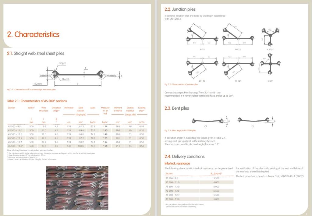
AS 500® Straight web steel sheet piles

Design & Execution Manual. AS 500® straight web steel sheet piles

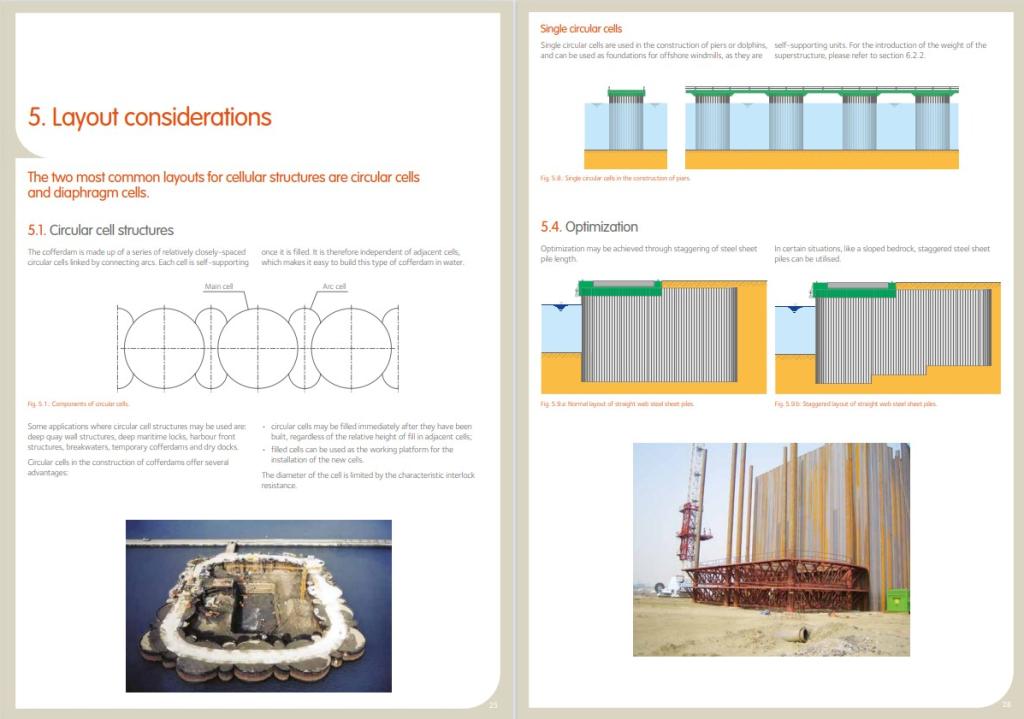
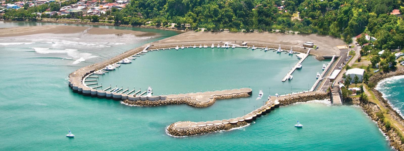
Cellular cofferdams can be designed as self-supporting gravity walls not requiring any supplementary waling and anchoring. They can be founded directly on bedrock, without any embedment. They are economical solutions for works in deep waters, high retaining works, and long structures.

The Applications of Straight Web Steel Sheet Piles fall into two categories: for temporary works and for permanent works

1. Temporary Works: 
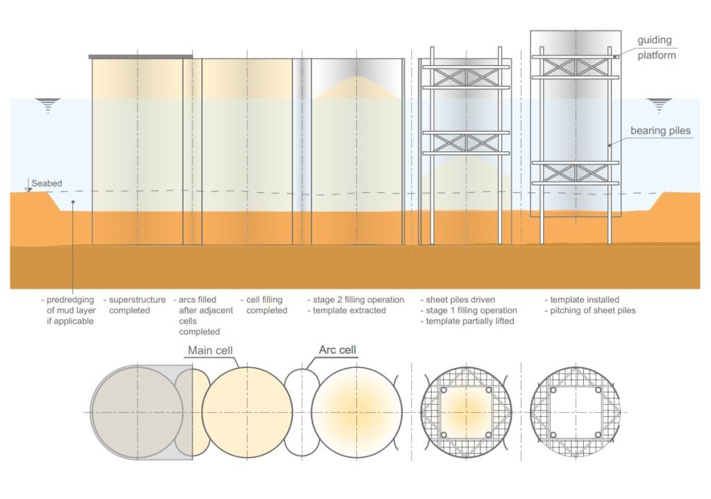
  • Massive Cellular Cofferdams: Formed by a series of individual sheet pile cells, these cofferdams enable large and deep excavations to be carried out in dry areas or alongside riverbeds, often reaching down to bedrock. 
2. Permanent Works: 
  • Quay Walls: These serve as both retaining walls and berths for ships, commonly used in the maritime-engineering sector.
  • Piers and Jetties: Structures used for berthing ships on both sides.
  • Dolphins: Single-cell structures used for berthing or guiding ships.
  • Breakwaters: Structures designed to protect harbors, although berthing is typically not possible. 

Download

en English AS 500 – Design & Installation manual.pdf
Straight web steel sheet piles
Layout considerations
Design
Installation phases of circular cell structures
Pause Play

Characteristics for AS 500® Straight Web Steel Sheet Piles

Discover a comprehensive catalog featuring straight web steel sheet piles designed for both temporary and permanent works. These sheet piles boast exceptional watertightness thanks to their robust interlock design, eliminating the need for additional measures. Adhering to strict geometric tolerances according to EN 10248 standards ensures precision and consistency in every application. 

Explore junction piles constructed with AS 500® sections, welded in accordance with EN 12063 standards. Bent piles undergo rigorous verification to ensure structural integrity and performance. Whether you require specialized coatings, handling holes, or specific steel grades, our catalog provides detailed information to guide your selection process.

Layout considerations

The two most common layouts for cellular structures are circular cells and diaphragm cells.

Our AS 500® straight web steel sheet piles offer versatile layout options:
  • Circular Cell Structures: Ideal for various applications like quay walls and breakwaters, circular cells provide immediate filling after construction and can be used as working platforms. Recommended junction angles ensure optimal stress distribution.
  • Diaphragm Cell Structures: Consisting of two circular arcs joined by 120° junction piles, diaphragm cells require embankments for water construction. Closure cells ensure stability at the structure ends.
  • Additional Layouts: Options include circular cells without rear arcs, cloverleaf-type cells for stability, and single circular cells for specific purposes like offshore windmill foundations.
  • Optimization: Staggering steel sheet pile length optimizes diaphragm cell performance, especially on sloped bedrock. 

Design Guidelines for AS 500® Straight Web Steel Sheet Piles

Functional Characteristics and Stability

Horizontal forces from water and earth pressure are countered by self-weight and lateral passive earth pressure. Straight-web sheet piles support pressures within cells, considering sliding, tilting, and bearing capacity.

Design Criteria: 

  • Soil Conditions: Ensure sufficient bearing capacity; improve cohesive soil with suitable material. 
  • Horizontal and Vertical Loads: Straight web piles resist horizontal loads only; minimize water pressures. 
  • Earthquake Effects: Analyze additional forces during earthquakes, considering confined pore water for cohesive soils. 
  • Durability: Corrosion affects structures, with thickness reduction based on design life.

Construction of cellular structures for AS 500® Straight Web Steel Sheet Piles

Usual construction sequence for circular cell structures: 

  • pitch the main cells, using a template; 
  • drive the sheet piles in the main cells; 
  • fill the main cells; 
  • pitch the connecting arcs between two completed main cells, using a template; 
  • drive the connecting arcs; 
  • fill between the main cells.

Main cells can be independently backfilled, with the template ensuring stability. Backfill should reach at least 2/3 of the cell height before template removal. Filling from the center prevents unbalanced loads, typically using conveyor belts or hydraulic fills. Sheet piles develop tensile resistance during filling, causing a slight diameter increase (barrel effect). Granular soils like well-graded sands or gravels are recommended for fill material, aiding in correct design parameters and consolidation. Compacted fill may require considering additional earth pressure, and vertical drains can expedite consolidation.